For the specification of an active funcional specification, the following steps can be consulted as a guidance:
- Create a facility, import & parameterize a scheme
- Create a state space
- Create states
- Create rules within the states
- Create a marker function
- Create and assign marker rules within the states
- Create an evaluation-metric for the state space
- Generate a textual document of the avtive functional specification
1. Create a facility, import and parameterize a scheme
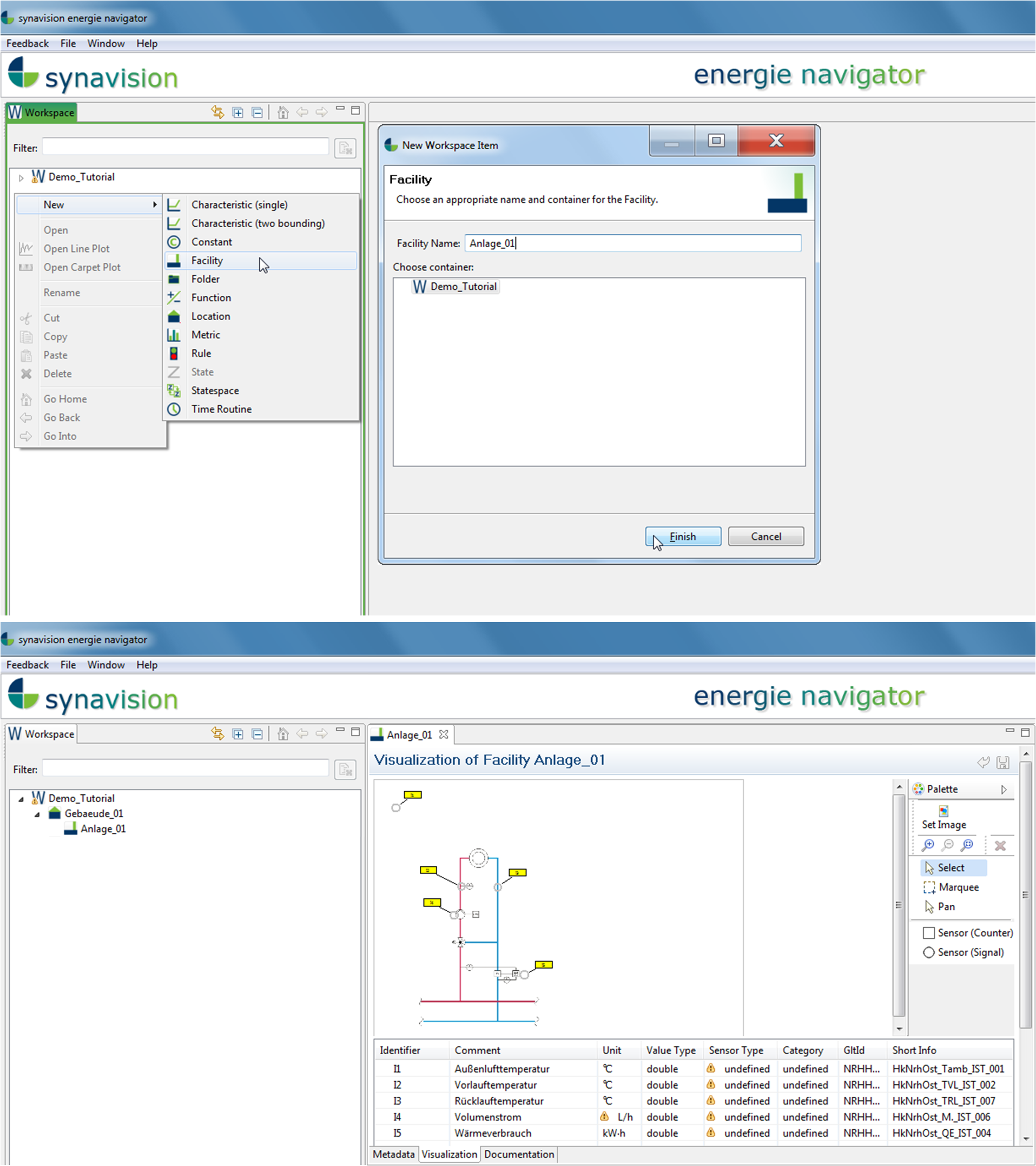
Creating an active functional specification starts by establishing a facility, whose functionality is to be analyized during the further procedure. By a right-click in the workspace „Specification“ a new facility can be created via „New“ and „Facility“. In the following window, the facility can be named. The created facility can then be found below „Specification“. By double-cklicking on the facility, further adaptations can be conducted in the editor window. This could be for example a textual description in „Metadata“ or the adding of a graphic in „Visualization“ and its parameterization with sensors if already available (see facility). Analogous a building can be superordinated to the facility.
2. Create a state space
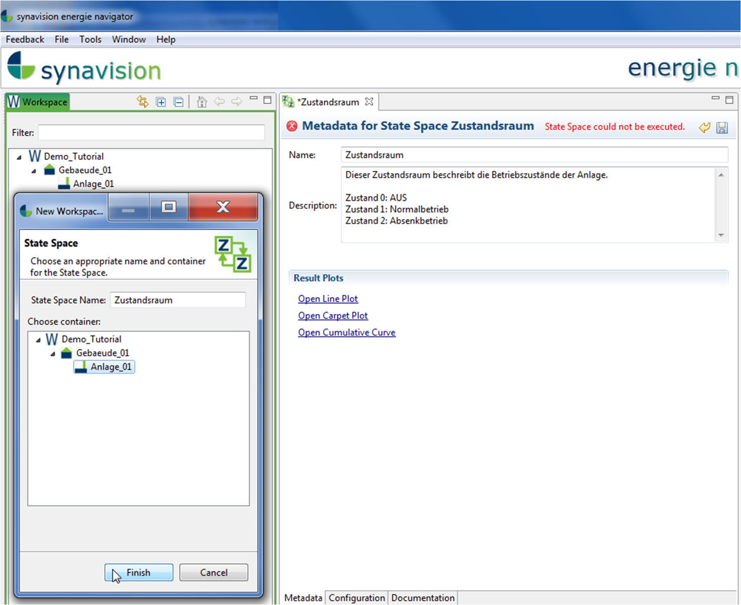
The next step is to create a state space by right-clicking on the facility via „New“ and „State Space“. The allocation of the state spaces into a file, named „AFS“, is recommended. Name the state space adequately. A description as well as further optional information can be added in „Metadata“ and „Documentation“. The visual evaluation of the state space and its states can be conducted later in „Configuration“.
3. Create states
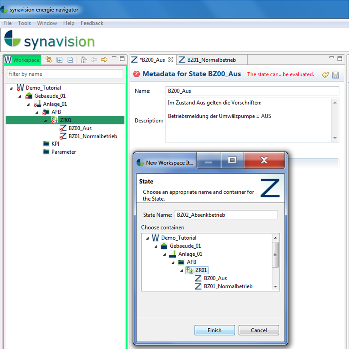
Now the state space has to be complemented by states. A new state can be created by right-click on the state space via „New“ and „State“. Similar to before, a description as well as further optional information can be added in „Metadata“ and „Documentation“. In „Configuration“ you assign a marker rule to the state (step 6).
For the following example, three states of a heating circuit are defined: OFF, Normal and Setback.
4. Create rules within the states
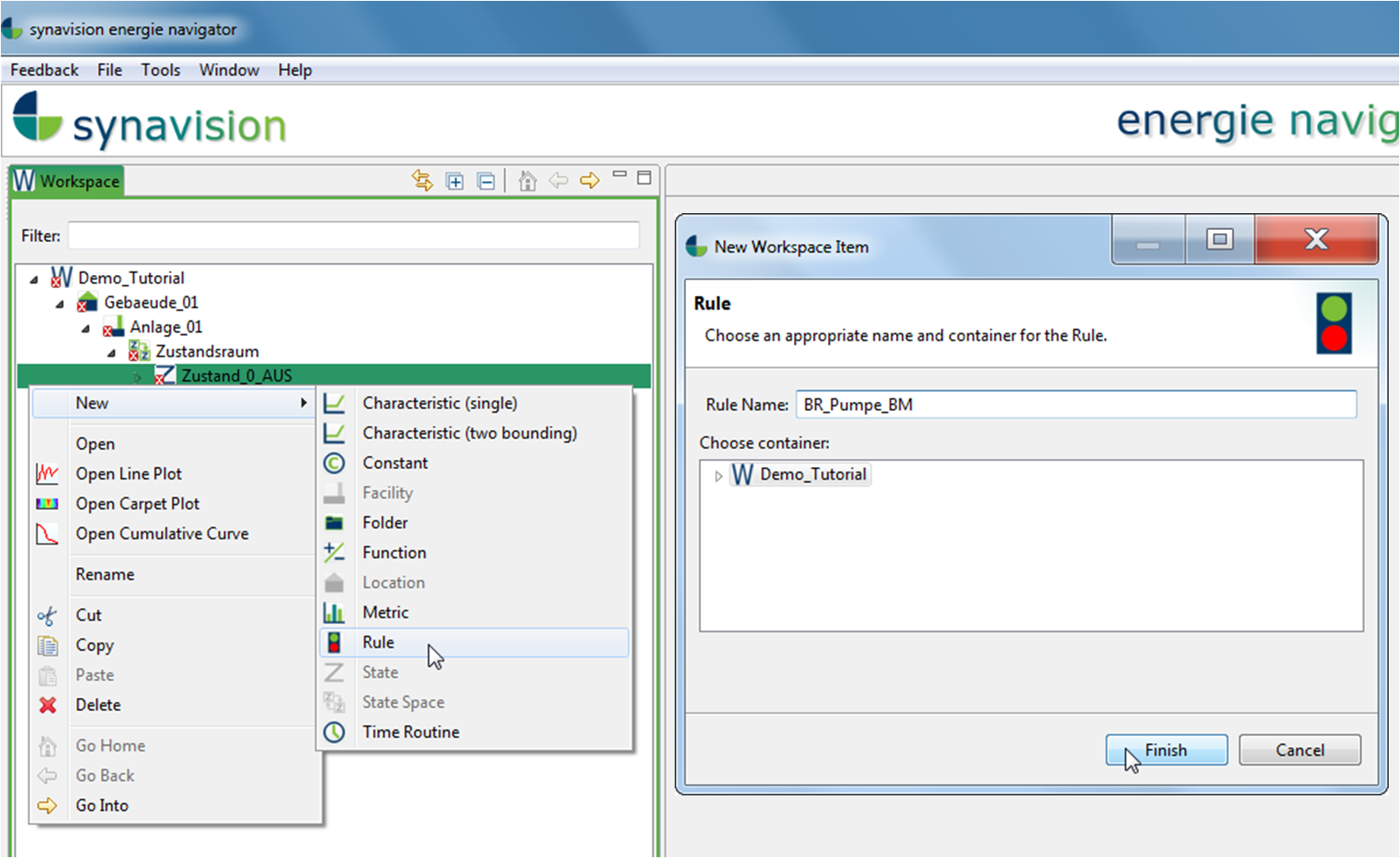
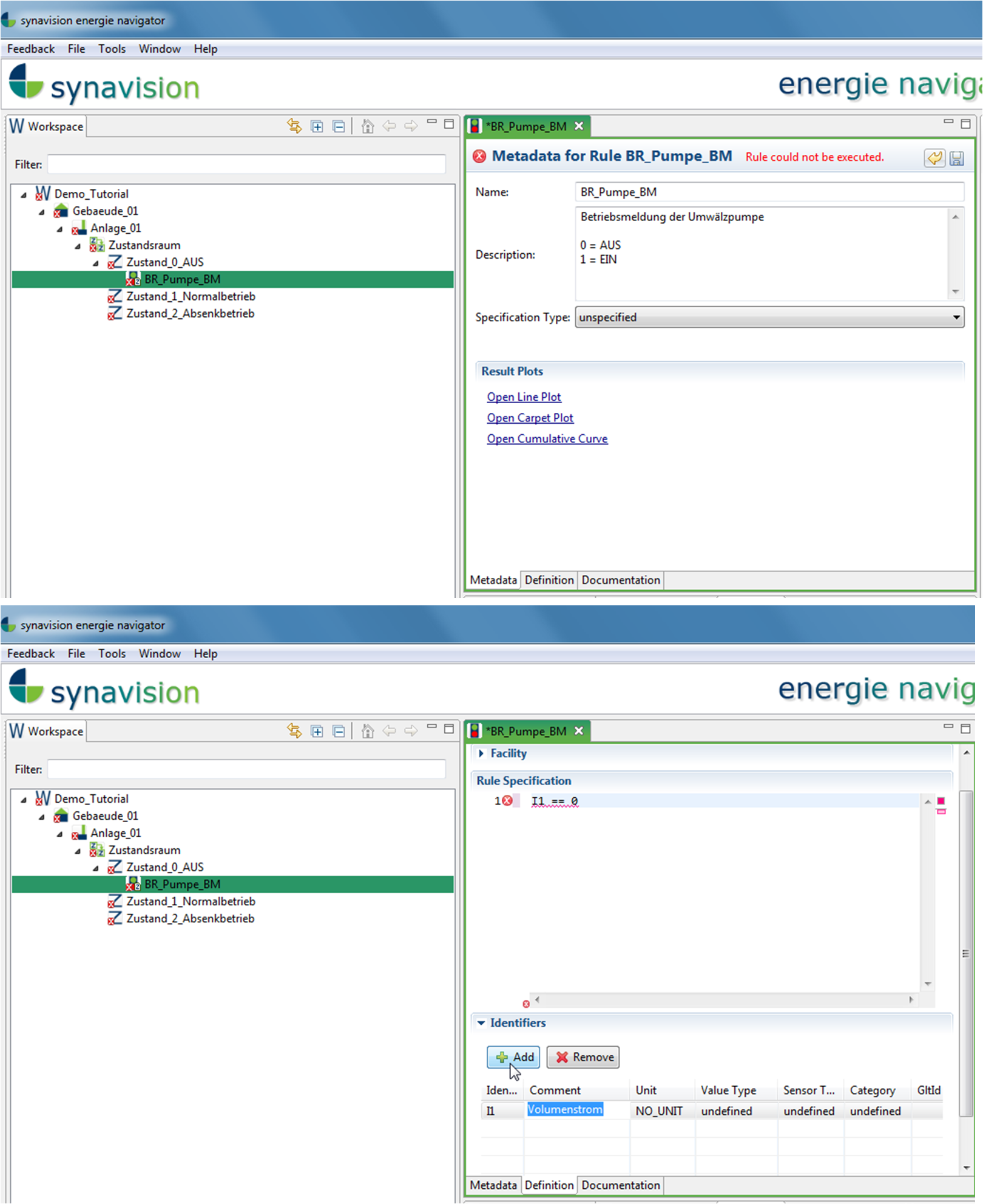
As can be seen in the example below, the property of the pump could be defined as one rule (R) for the state OFF of the heating circuit. For the state OFF, the pump is out of operation so turned off. This property could be described by the volumetric flow rate. If the pump is out of operation, its flow rate is zero.
By right-clicking on a state, a new rule can be created via „New“ and „Rule“. In the editor window a description as well as further optional information can be added in „Metadata“ and „Documentation“.
In „Definition“, the rule can be defined by the available means. In the given example, the rule is defined to be valid, when the volumetric flow rate equals 0 L/h. Therefore an Identifier, with the annotation „flow rate“, is created in the first instance. The automatically allocated reference variable can now be used in the definition:
I1 == 0
Keep in mind, that the rule will only be calculated, when the actual operational data of the flow rate has been assigned to the reference variable I1.
5. Create a marker function
Create a marker function as a data point for the state space (state indicator). The state indicator specifies, in which state the facility is in at a certain point of time. In this example of the heating circuit, the building automation does not provide a state indicator. Therefore a maker is defined as a function by other reliable indicators. Those are the ambient temperature and the time routine from the normal operating state.
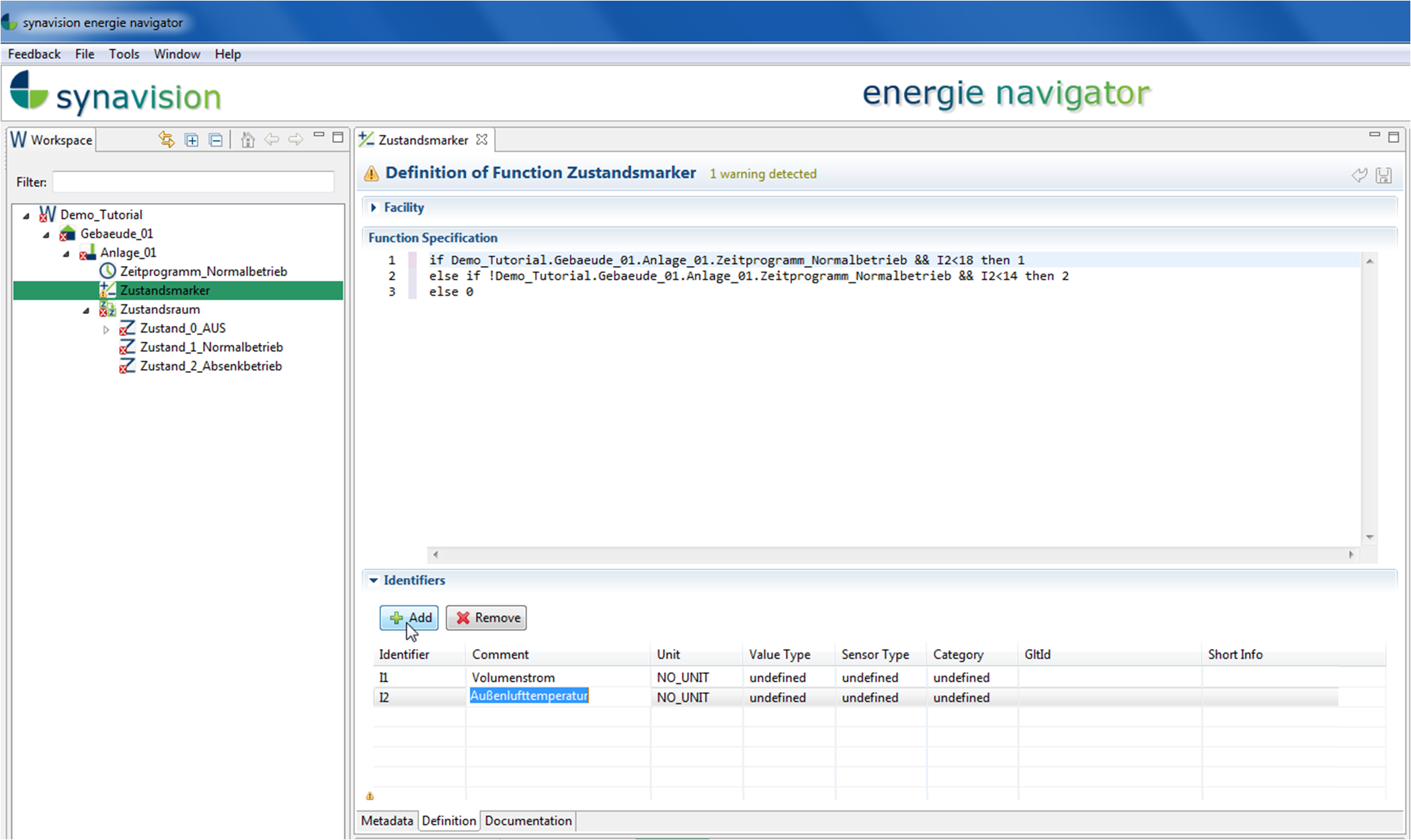
The state „Normal“ (state 1) applys, when the facility persist in the normal operating state and the ambient temperature is below the threshold value for the day of 18°C. The state „Setback“ (state 2) is valid outside of the time routine for the normal operating state and additionally the ambient temperature is below the threshold value for the night of 14°C. The third state „OFF“ (state 0) applys, when the other states do not apply.
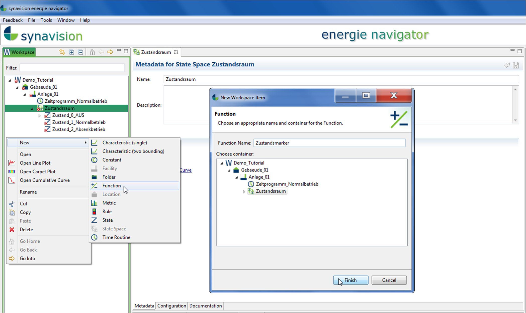
Such a state indicator can be described for example by an „if a then b else c“ function. Therefore a new function has to be created by a right click in the workspace „Specification“, preferably in the file „AFS“, via „New“ and „Function“. After naming the function, the state indicator appears in the editor window. In „Definition“ the specification of the function can be inserted. Therefore an Identifier with the annotation „ambient temperature“ is added in the first instance. The assigned reference variable can be used in the definition. The time routine will be directly inserted from the active functional specifiaction via drag&drop to the requiered place in the specification of the function:
if time routine_normal && I2
Keep in mind, that the rule will only be calculated, when the actual operational data of the ambient temperature has been assigned to the reference variable I2.
6. Create and assign marker rules within the states
Now for each state, a marker rule has to be created, that is specifically valid when the corresponding state applies according to the state indicator. This means, that in this example the marker rule for the state „OFF“ (SI_00) is valid, when the state indicator displays the value 0. For the state „Normal“ the corresponding marker rule (SI_01) is valid, when the state indicator displays the value 1 and so forth.
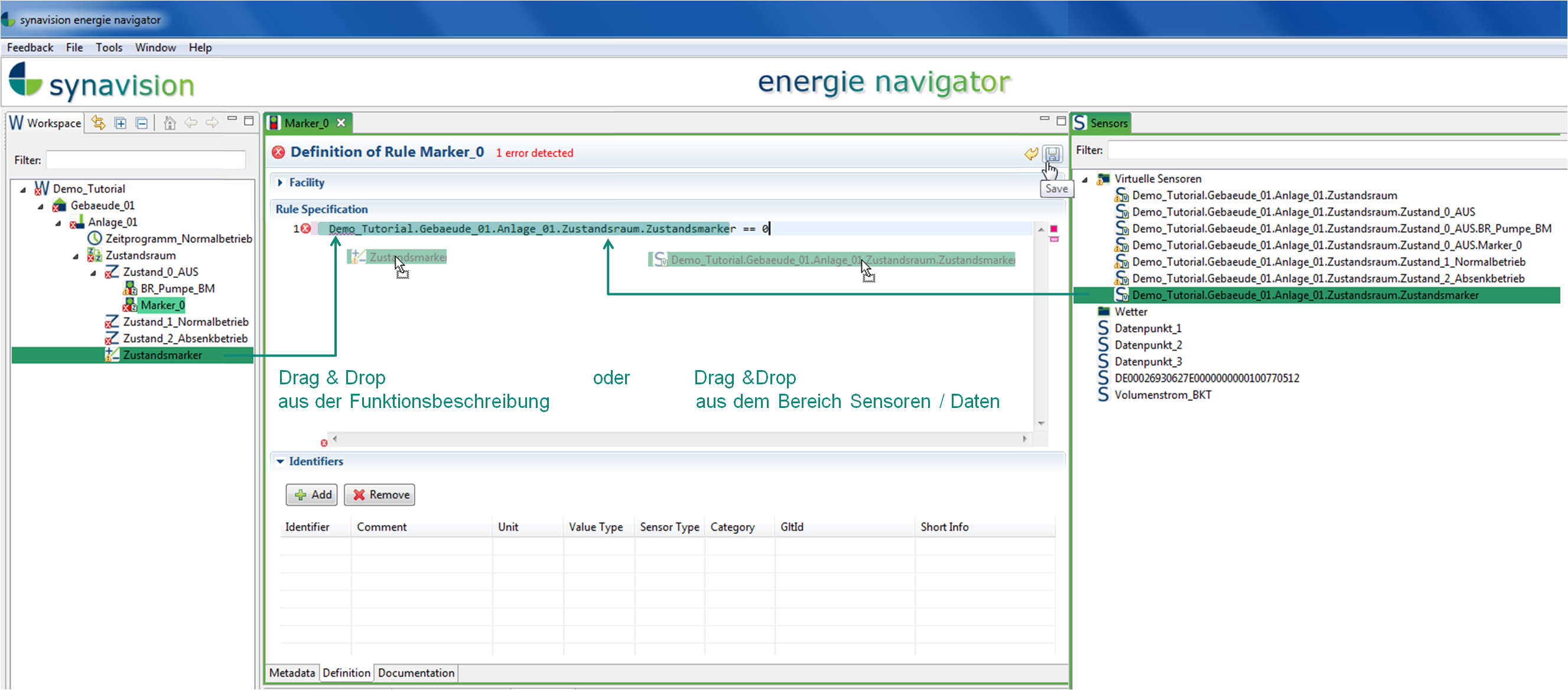
The marker rule can be created by right-clicking on the individual states via „New“ and „Rule“. The marker rules should be named adequately, e.g. SI_00, SI_01 and SI_02. Following, the marker rules can be defined in the editor window in „Definition“. In the state „OFF“, the marker rule should be valid when the facility persist in this state according to the state indicator. Therefore, in this marker rule the state indicator should be set equal to 0.
Demo_Workspace_en.Heating_Circuit.HC02.AFS.SS01.SI_virtual == 0
The state indicator is a virtual sensor. Virtual sensors as well as time routines can be directly used in rule definitions by drag&drop (no creation of an identifier with its reference variable is needed beforehand).
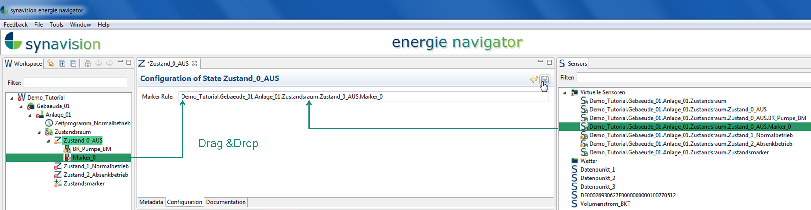
Also the newly defined and saved marker rule SI_00 appears in form of a virtual sensor in the section „Data Points“. Now the states can be opened in the editor window by a double-click. In „Configuration“ the corresponding marker rule can be assigned to „Marker Rule“ by drag&drop. For the state „OFF“ it would be the marker rule „SI_00“.
7. Create an evaluation-metric for the state space
The states will be evaluated individually by the digitale testbench. Therefore each rule of a state will be tested for its validity at every point of time. The individual state is valid for one point of time, when all corresponding rules are valid at this moment.
For the evaluation of the state space, all rules of the current state will be evaluated. When the respective state is valid, also the state space is valid.
The results for the evaluation of the state space and the individual states can be displayed in form of carpet plots in „Configuration“ of the state space. Furthermore the results can be found in the section „Data Points“ as virtual sensors.
The evaluation-metric of the state space provides the number of valid values in relation to the total number of possible values of a defined time period. Therefore a new metric can be created in the active functional specificationn by a right-click and via „New“, „Metric“. After choosing a name, the metric can be edited in the editor window. In „Configuration“ the base function „Evaluation“ and the requiered time period (e.g. „day“) is chosen. Furthermore the „Interval“ is set to „open“. Then the virtual sensor of the state space is added by drag&drop to the intended place.
As soon as the metric is saved, it will be calculated by the PTB and indicates the number of valid values per day expressed as a percentage. This enables a quick evaluation, if the rules and states of a facility have been valid for the corresponding state space, for example for at least 80% of all checked points of time.
The evaluation metric can be illustrated by a cumulative curve to indicate, how many days comply with the defined minimum value of 80%.
8. Generate a textual document of the active functional specification
Via „Create Specification Document“ under „File“, a textual document of the functional specification can be exported.